I have to admit, I haven’t thought about baud rate in quite some time. In my daily work I have moved ‘up the stack,’ and can safely assume that someone else has done the work to ensure that the information I send between software components gets to its destination as intended. It’s good, however, to understand how this reliability comes about, and a basic understanding of the role baud rate and bit rate helps.
The Challenge of Streaming 1s and 0s from Point A to Point B
It turns out that getting a signal from one end of a piece of wire or fiber to the other is pretty tricky, especially with increasing line length and transmission rate. The important thing to know is that the signal that comes of the line is not exactly the same as the signal that went in. See the figure below:
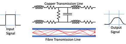
Figure 1: Transmission Line Characteristics
From the figure we can see that the cooper cable of the transmission line is a lot more complex than a straight connection. The length of the cable adds resistance, induction, and capacitance components which distort the signal as it travels.
In the case of optical fibre, the multiple paths photons can travel (even with single mode fibre) have different lengths, stretching and distorting the signal. The output signal shown is smaller and less defined than the source signal and it is delayed with respect to the timing grid.
The big advantage that optical technologies have over copper technologies, apart from lower loss for a given length, is less electromagnetic interference. Any single electrical signal flowing down a wire will emit some of the signal as electromagnetic energy, which can be picked up by other conductors (wires) and converted back into an electrical signal. This means that foreign signals may also be present on the transmission line, as well as the original signal. A key requirement is to be able to ensure the required signal can be distinguished from the unwanted signals (also known as “noise”) at the receiving end.
The “Symbolic” Nature of Data on the Wire
The challenge with data transmission is to get a signal from point A to point B, carrying as much information as possible, in a reliable manner. Note that the 1s and 0s we send as application developers may have different representations while they are in transit or ‘on the wire.’ For that reason when talking about baud rate we talk about symbols and not bits. Symbol rate is effectively the baud rate. I’ll explain the conversion from bit rate below, but with that in mind, the encoding process needs provide the following functions:
- End-to-end timing to ensure the receiver samples the signal at the correct time to reliably detect the transmitted symbols.
- Maximize the signal-to-noise ratio so that the signal is recoverable at the receiver.
- Reduce the symbol rate (baud rate)
- Minimize signal bandwidth
- Maximize signal bit rate
Baud Rate
Baud rate, then, is the measure of the number of changes to the signal (per second) that propagate through a transmission medium. The baud rate may be higher or lower than the bit rate, which is the number of bits per second that the user can push through the transmission system. Bits will be converted into baud for transmission at the sender side and the reverse conversion will happen at the receiver end so that the user receives the bit stream that was sent. A few simple definitions before we move ahead:
- Bit rate – the number of binary ‘bits’, 1s or 0s to be transmitted per second
- Baud rate – the number of line ‘symbols’ transmitted per second
- Channels – the number of transmission channels
So to convert bit rate to baud rate you multiple baud rate by the number of bits per symbol by the number of channels being used:
Bit rate = baud rate * bits per symbol * Channels
Next I’ll explain how baud rate and bit rate apply to Solace appliances.
Connecting to Solace PubSub+ Event Broker Appliances
All Solace PubSub+ Event Broker appliances use ethernet connections for data and management connections, and provides an RS232 serial port so you can configure things before an IP address is assigned. I will start by explaining the simpler RS232 and move on to 1GE ethernet.
RS232 (Serial Console)
Serial communication via a terminal server to the Solace 3xx0 Console, via RS232, is one place where you will find baud rate mentioned within the Solace documentation. RS232 is one of the oldest and simplest computer communication methods. It is pretty slow, with speeds measured in kilobits per second rather than megabits or gigabits, and it is used for initial configuration of Solace hardware, an action that is typically carried out just once upon installation. The entire RS232 standard is not required for a console connection, so I’ll stick to the relevant parts.
The RS232 specification is applicable to copper transmission only and does not require any specific ‘standard’ of copper cabling. It is an asynchronous, serial communications protocol that transmits individual ‘data words’ between computer systems. While a data word is configurable between 5 and 8 bits, the usual settings are to transfer 8 bits – or a single byte – as the data word. The specification outlines the signal formats and signal levels as well as the interface specifications (connector types, pin assignments, etc.).
The protocol is pretty rudimentary by modern standards as the binary 1s and 0s are transmitted on the wire without any real encoding other than specifying the voltage levels for a 0 and a 1. The specification has information that is transmitted byte by byte – each byte delineated by a start bit and stop bit – and the standard allows for an optional parity bit for detection of bit errors.
In its simplest form, bi-directional RS232 communication needs two signal wires and a ground reference. This is shown, between two computers, in the following figure.
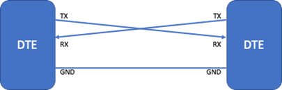
Figure 2: RS232 DTE-DTE Connection
The signal transmitted is shown in the next figure, where a ‘space’ or a ‘0’ being sent as a positive voltage between +5 volts and +15 volts and a ‘mark’ or a ‘1’ as a negative voltage between -5 volts and -15 volts.
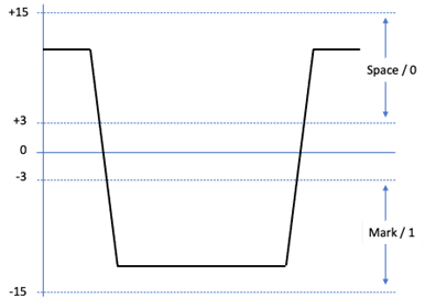
Figure 3: RS232 Line Levels
A byte of information is signaled by enclosing the byte with start and stop bits and declaring the idle state of the signal line. This means that clock signals do not need to be propagated end-end and that, as long as the baud-rate is agreed between the sender and the receiver, the receiver can start its ‘clock’ on receipt of a start bit.
The RS232 standard also allows a very primitive form of error checking in the form of a parity bit. This can be used to indicate that an error has occurred in the data word that contains the parity bit. The parity bit can be set to maintain an even or an odd set of 1s in the data word. For example, if set to even parity and the data word contains 3 x 1s then the parity bit will be set to 1 to maintain the even number desired. If even parity is assigned and a data word is received with an odd number of bits and is set to 1, then there is an error.
The parity check does not detect all errors though, like in the example where ‘bit 4’ moved from 0 to 1 and bit 7 moved from 1 to 0. In this case, it is optional and often not used.
The Solace console has the basic RS232 configuration:
- 8 data bits
- 0 parity bits (turn Parity checking off)
- 1 stop bit (RS232 allows 1, 1.5 and 2)
- No flow control
- Baud rate configurable
- valid values: 110, 300, 1200, 2400, 4800, 9600, 38400, 57600 or 115200
- default 115,200 bps
On the wire, a transmitted byte will appear as shown (for ASCII ‘A’):
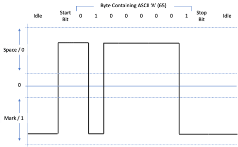
Figure 4: RS232 ‘Framing’
From the trace, you can see that the line in its idle state is held at the negative state, or ‘mark’. The receiving clock will not run until the line transitions to a positive state, or space, and it will then run at the agreed rate so that it can sample the signal at the correct points. The stop bit is a single bit width ‘mark’. This type of coding means that even if I send a set of repeating bytes with all 0s or all 1s, the receiver will still see a ‘clock start’ for every byte, so can keep time with the sender.
The usable baud rate setting of the RS232 connection is drastically affected by the length of the cable that is used between the Solace appliance and the data centre terminal server. The higher the baud rate that is configured, the shorter the cable length. The default 115,200 baud setting is designed for very short cable length to a ‘top of the rack’ terminal server found in newer data centres. For data centres where larger terminal servers are deployed that serve a whole suite of racks, the default should be changed to allow longer cables and reliable communication. The value of 9,600 is a common terminal server speed for this style of terminal server/console deployment.
To change the baud rate of the serial console, you can issue the following commands in ‘enabled’ mode:
solace# configure
solace(configure)# console baud-rate <baud-rate>
It should be obvious, but both ends of the RS232 connection must have the same configuration.
Gigabit (1000BaseT) Ethernet
I’m going to talk about 1 gigabit ethernet (GE) since most 10 GE connections are over fibre these days. Gigabit ethernet is used for the management connections to the Solace 3×00. A detailed description of the entire GE data path is beyond the scope of this article, and there are no configuration tweaks available, but enough will be covered so that an appreciation of bits and ‘bauds’ (or symbols) can be reached.
The standard allows 1 gigabits per second of data transfer using CAT 5 copper cables installed in most data centres and buildings. It is pretty much the ‘connect and it works’ system for large scale communication in most environments today. While your PC might connect over Wi-Fi at 50 Mbps, 100 Mbps, or perhaps 200Mbps (using 802.11ac Wi-Fi), the backhaul connection to the access point is likely to be gigabit ethernet. So, given that in the previous section we said that RS232 could only sustain 115.5 kilobits per second over quite short distances, how does gigabit ethernet allow buildings to be wired up?
The first clue is in the cable. By defining the standards for the cable to, ethernet designers have a known and proven transmission system. CAT 5 was chosen because it was already everywhere in data centres and buildings because it was specified for the previous 100Mbps ethernet standard. The cable itself is designed to work at up to 125Mbps which is required for 100Mb ethernet. Reusing the existing infrastructure would help to significantly reduce the cost of the upgrade from 100Mbps to 1Gbps and increase adoption.
The challenge for the 1GE designers was how to get 10x the information through the same copper infrastructure with similar reliability and useable communication distances.
100mbps ethernet uses what is called 4B/5B communication and adds bits to the data flow for error detection and correction. It also uses a separate pair of wires for transmit and receive which is similar to the previous RS232 communication between DTEs.
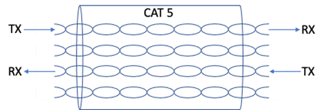
Figure 5: !00Base-T Uses Separate TX / RX Pairs for Full Duplex Transmission.
To reuse the cabling, the 1GE designers used a few optimizations to make 10x the data volume fit into the same transmission capacity:
- The first was in the use of hybrid circuits. Hybrid circuits were designed and used in telecommunication circuits for a very long time for two-way speech to be sent down a single pair of wires.
- The second was to use spare capacity within the existing environment. That is, the designers took advantage of the fact that CAT5 cable has 4 pairs. Splitting the transmitted data into 4 slices allows the data rate of each slice to be reduced to 250Mbps (1000Mbps/4).

Figure 6: 1000Base-T Uses All Four Pairs with Hybrid Circuits to Allow Full Duplex Transmission
Skipping a large amount of detail on bitstream scrambling, convolutional/trellis encoding and Viterbi decoding, the standard then uses a PAM5 modulation scheme to transmit data 2 bits per symbol. This reduces the rate to 250M/2 = 125M baud (symbols) per second which is within the capacity of the environment.
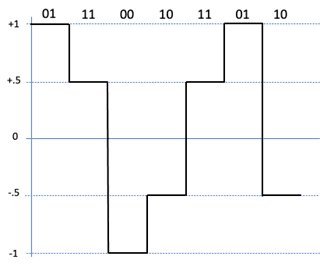
Figure 7: Gigabit Ethernet 4D-PAM5 Line Levels to Support Two Bits Per Symbol + Control.
The PAM5 scheme is used instead of PAM4 – only 4 signal levels are needed to represent all combinations of two bits – in order to allow extra symbols for signaling and control.
The use of convolutional coding and Viterbi decoding provides error correction for the transmission path. This makes up for the reduced voltage difference between ‘states’ (0.5 volt rather than 1 volt used for 100Mbps ethernet) that would drive down the signal-to-noise ratio and add to the errors experienced. Unlike the RS232 example above, this is error correction and it can cope with multiple bit errors. The error correction effectively adds about 6dB to the signal-to-noise ratio allowing gigabit ethernet to run similar distances on CAT5 as 100Mbps ethernet.
Summary
Baud rate is the measure of the number of changes to the signal (per second) that propagate through a transmission medium. The baud rate may be higher or lower than the bit rate, which is the number of bits per second that the user can push through the transmission system. Bits will be converted into baud for transmission at the sender side and the reverse conversion will happen at the receiver end so that the user receives the bit stream that was sent.
A few simple definitions:
Bit rate – the number of binary ‘bits’, 1s or 0s to be transmitted per second
Baud rate – the number of line ‘symbols’ transmitted per second
Channels – the number of transmission channels
To Convert:
Bit rate = baud rate * bits per symbol * Channels
Visit the solace documentation page to learn more about configuring the baud rate for a PubSub+ Event Broker appliance.
Explore other posts from category: Uncategorized


Subscribe to Our Blog
Get the latest trends, solutions, and insights into the event-driven future every week.